|
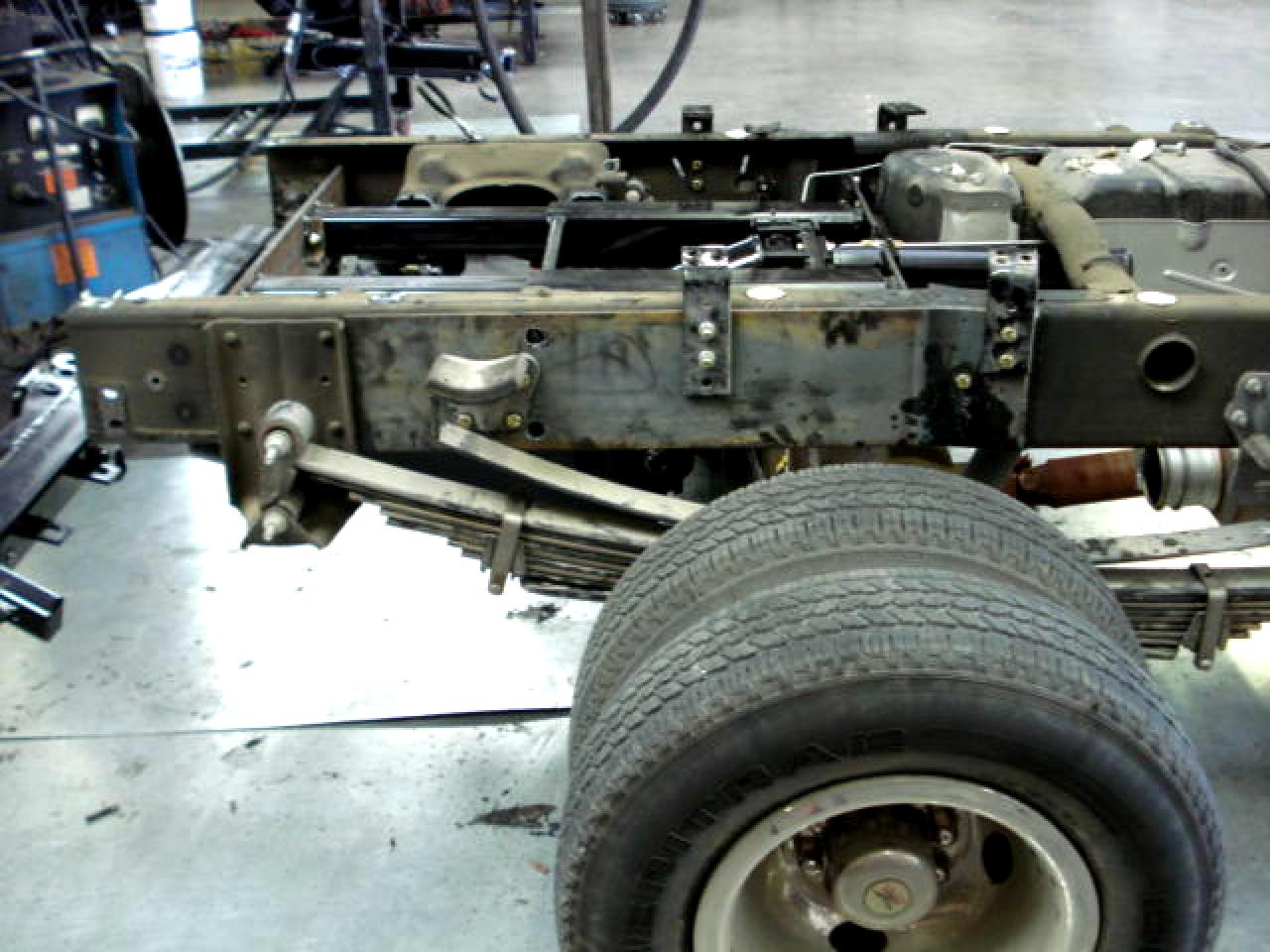
WHEEL-LIFT INSTALLATION (PICKUP) 1.) Rear Leaf Springs: We strongly recommend that you increase the number of leafs in the rear main springs before you begin the installation process. In most cases we have found that these additional leafs (Dodge - 4 leafs, Chev. - 3 leafs and Ford - 2 leafs), in addition to an in-cab controlled airbag system, will be adequate in most cases. The use of an airbag system has always proven to be far more effective than additional helper/overload springs. 2.) Remove Bed: Remove rear bumper, disconnect all lights and fuel fill hoses. Remove bed. Measure and note distance between frame rails for future reference. 3.) Remove rear crossmember / spare tire support: Support may be removed by saw cutting or torch cutting, (see figure 3-A). Note: On Dodge trucks, the left rear shock is mounted to the rear crossmember / spare tire support, you must cut rear crossmember / spare tire support, leaving the shock mount portion attached to frame as shown in figure 3-A, you can then reinforce the shock mount if you so desire.
4.) Reinforce Frame: We strongly recommend that you reinforce the rear section of your truck frame. Unless reinforced in strategic places, the pickup frame is more susceptible to bending or breaking. This can be done in a number of ways; (1) flat plating the outside of the frame rails, (2) boxing the frame rails, or (3) double channeling the frame rails. We at Hy-Tech Recovery Equipment Inc. do not claim to be experts at frame reinforcement. When installing lifts at Hy-Tech Recovery Inc. we chose to flat plate the outside of the truck frame rails, (see figure 4-A) This is by no means a statement that it is the only method or the best method. If you prefer a different method of reinforcing your frame, please feel free to do so. Regardless of the method you choose, Hy-Tech Recovery Equipment Inc. will not be liable for any frame damage or damage caused by it, whether you choose to reinforce your frame or not.
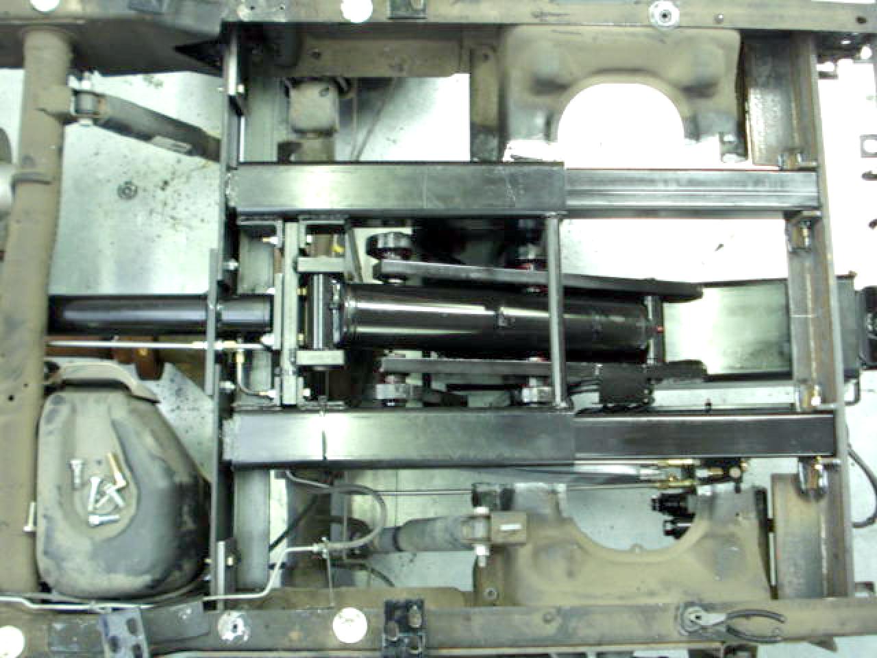
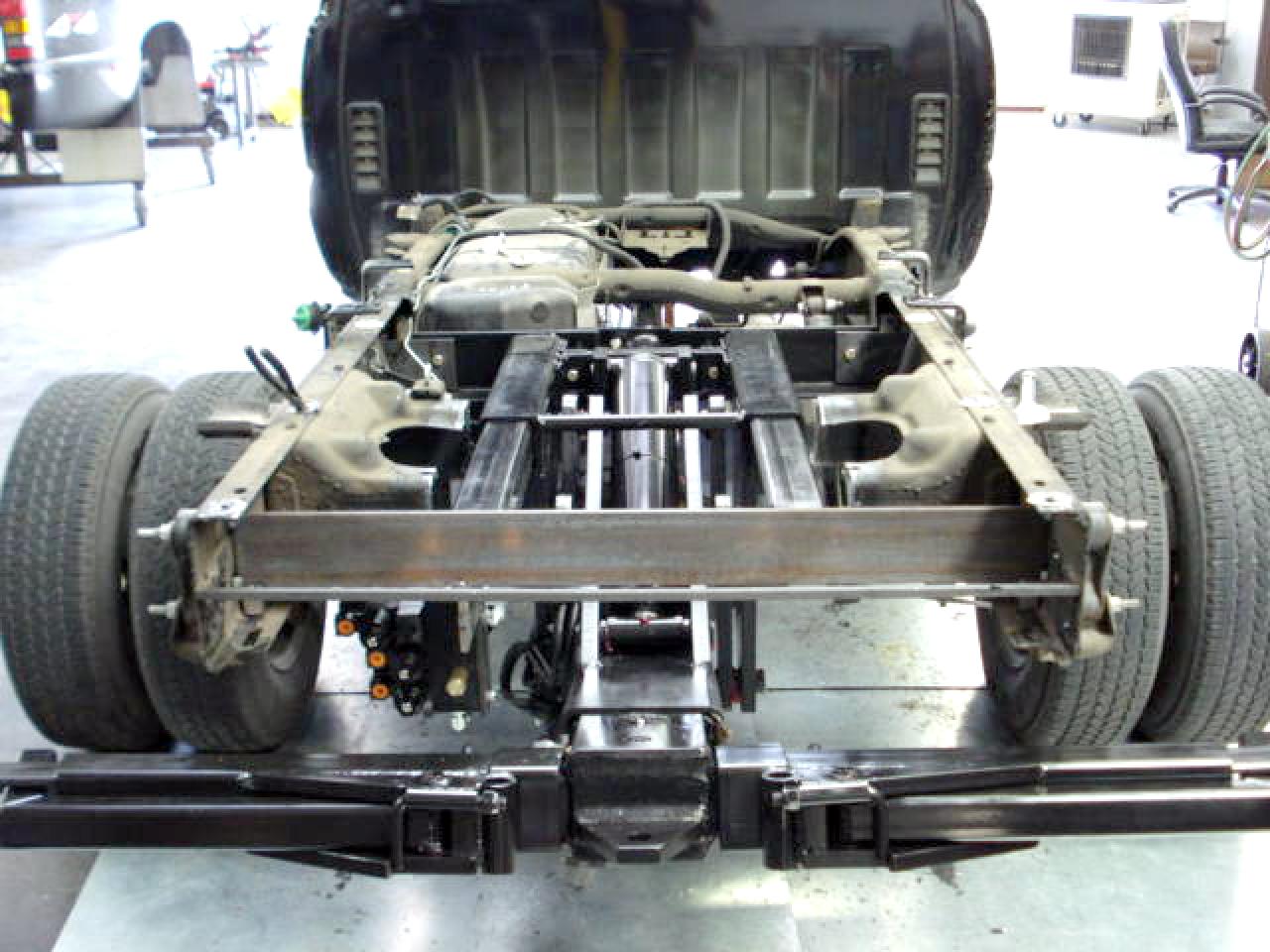
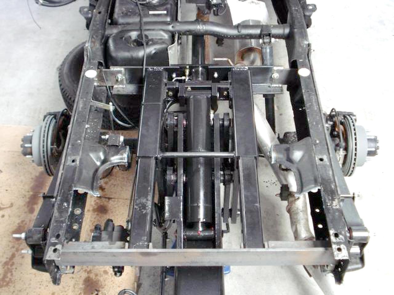
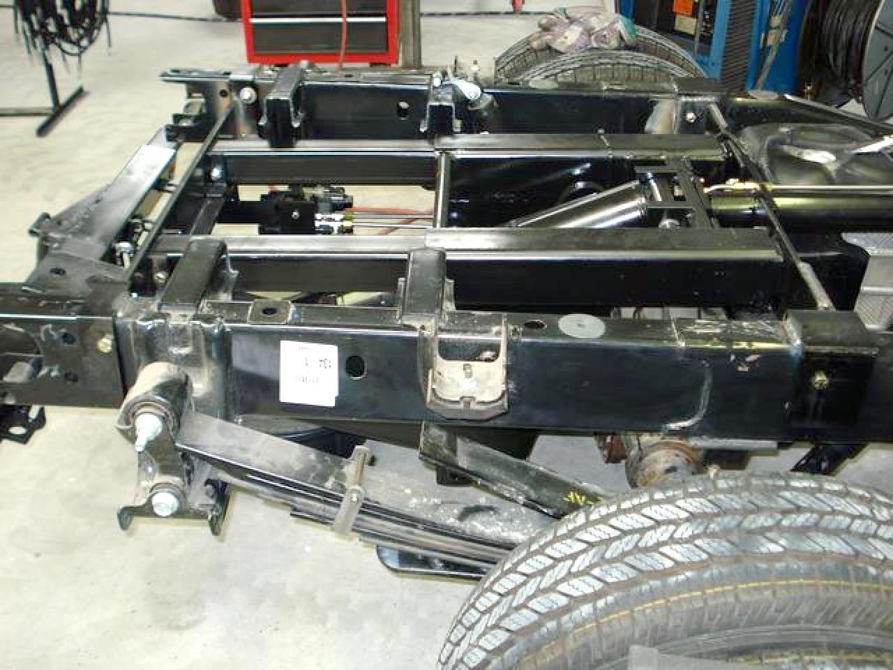
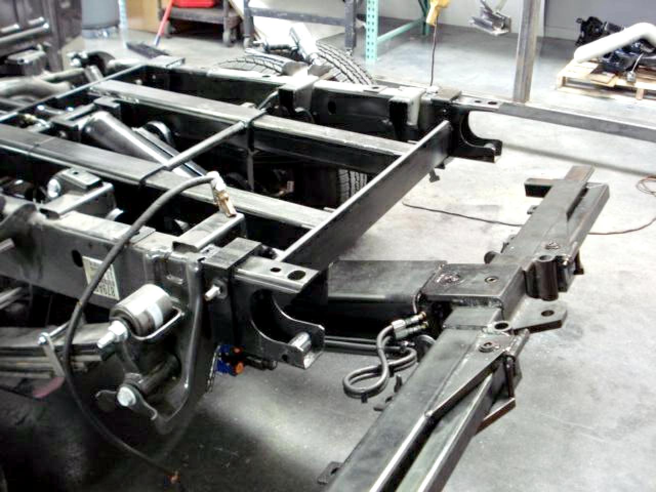
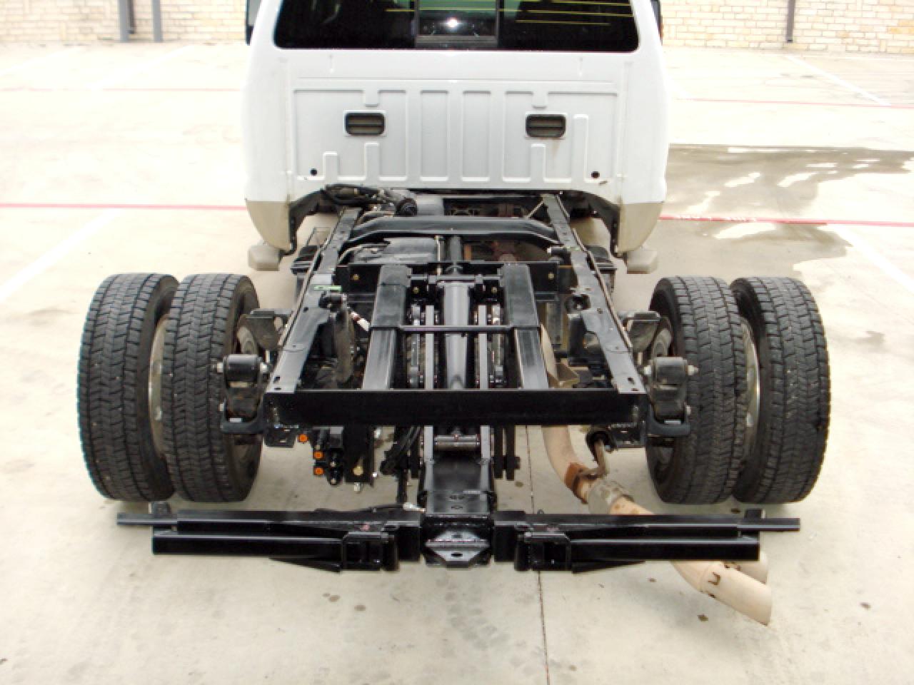
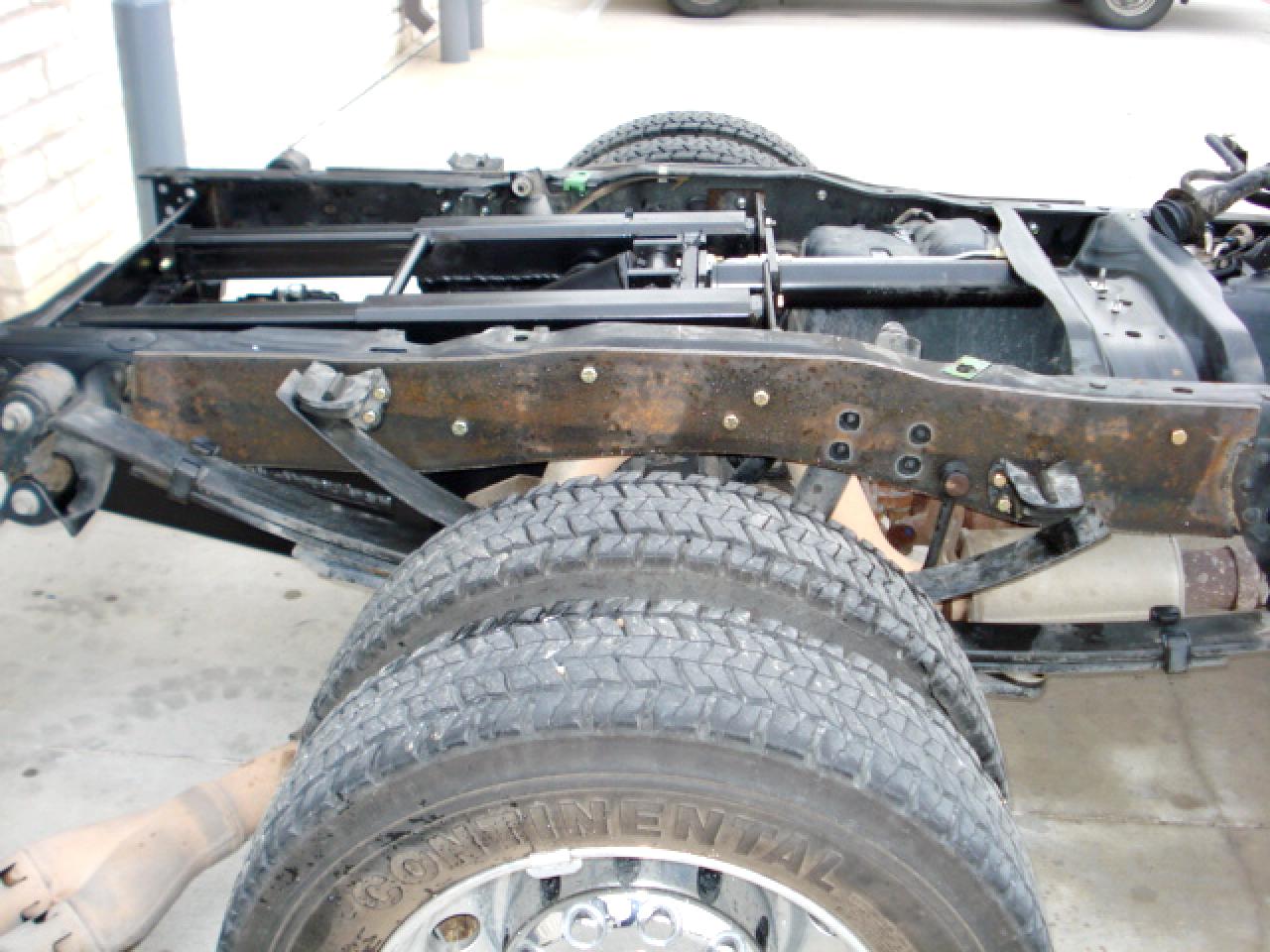
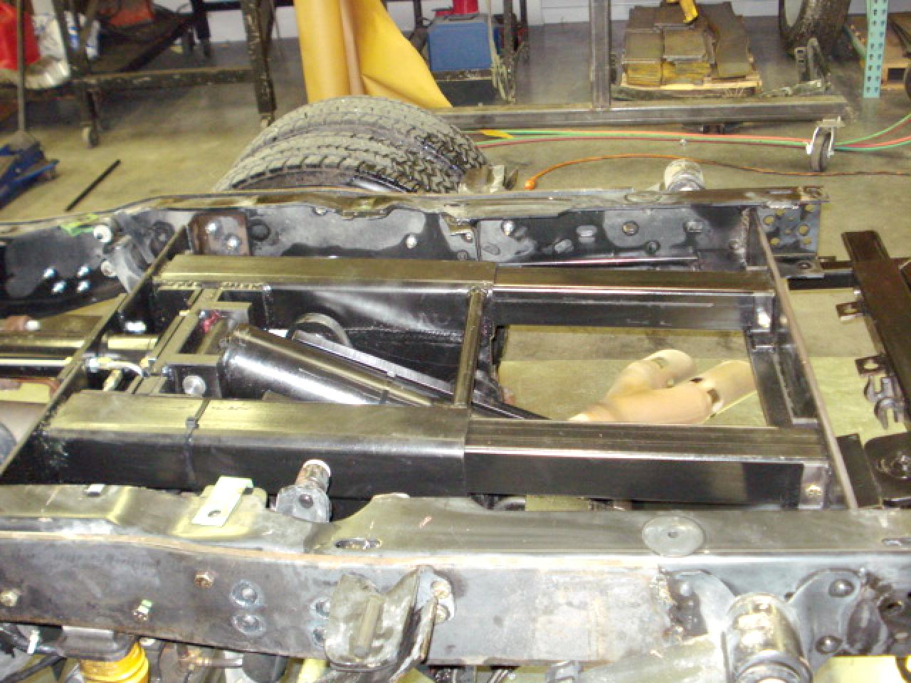
5.) Install Airbag System: Since the "airbag" system has been available for light duty trucks, it has been the most effective form of suspension upgrade available. We strongly recommend the use of an "airbag" system to stabilize the rear suspension. Detailed instructions are included with the kit. 6.) Installation Photos: 7.) Exhaust: Lower the tailpipe by disconnecting hanger brackets from the frame. This will allow the wheel lift to be positioned properly inside the frame rails. The position of the wheel lift installed inside the frame rails, may not allow the tailpipe to be reinstalled in its original position. It may be necessary to reposition the tailpipe in order to achieve adequate clearance from the wheelift. In some cases (depending on make, model & engine size) you will be able to lower and re-mount the tailpipe by extending the factory mounting brackets. In other cases you will have to eliminate the tailpipe and replace it with a turndown extension, or have your exhaust re-routed out the side or rear of truck. 8.) Mount Lift: Lower wheel lift in place and rest on the frame of the truck as shown in figure 8-A. The wheel lift must be centered between the truck frame members. Make certain you have adequate clearance between truck third member and wheel lift. Re-align truck frame members' to original dimension. Then square the unit to the frame and clamp into position. Now weld all around the rear angle mount and frame rails as shown in figure 8-B. The quality of the weld should meet or exceed AWS Dl.1 Structural Welding Code (this refers to making a structurally sound weld with one of the following processes: SMAW (ARC), MIG or TIG.)
9.) Forward Mounting Support: Mount forward mounting angle as shown in figure 6-A. 10.) Middle Mounting Support: install side mounting angles as shown in figure 10-A, using l/2" grade 8 bolts & nylon lock nuts.
11.) Reinstallation of Pick-up bed: The pickup bed is now ready to lower back onto the truck chassis. Be sure that everything is clear when lowering the bed onto the chassis. After pickup bed is in place, make certain you have adequate clearance between bed floor rails and the wheel lift slide rails and slide assembly. Install bed-mounting bolts. 12.) Hydraulic system hook up: A.) Engine mounted pump: Begin by connecting 1/2" high-pressure line to bottom port on wheel lift valve, marked "IN". Connect other end to pump port, connect 1/2" high pressure hose to top port on wheel lift valve marked "OUT". Connect other end to remote filler port marked "IN" (usually located near hydraulic reservoir), connect l/2" high pressure line to remote filter port marked "OUT". Connect other end to hydraulic reservoir. Connect 1 1/8" suction hose to hydraulic reservoir, connect other end to pump port. Note: Be certain all suction line connections are air tight, this will prevent air from entering hydraulic system during use. Fill hydraulic reservoir.
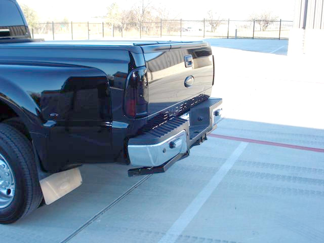
B.) 12 VDC Pump: Begin by connecting 1/2" high-pressure line to bottom port on wheel lift valve, marked "IN". Connect other end to pump port marked "OUT". Connect 1/2" high pressure hose to top port on wheel lift valve marked "OUT", Connect other end to pump port marked "IN". Fill hydraulic reservoir. 13.) Wheel Lift Controls: Included with your "Sneeker" wheel lift are (l) Power cord, (1) 15 ft. pigtail (for "In Cab" operation, if desired), and (1) 4 ft. pigtail. Install pigtails and pump wiring as shown in electrical wiring diagram. 14.) Initial Start Up: Plug power cord into control plug in rear of truck, operate controls, beginning with 1.) "Lift Down", 2.) "Ext. Out", 3.) "Forks Out", operate wheel lift functions until all air has escaped from hydraulic system. 15.) Reinstallation of Rear Bumper: Lower wheel lift, install rear bumper. NOTE: some modification of bottom of rear bumper may be necessary to fully retract wheel lift. Small, stock bumpers work best. No "Drop Down" or "V" bumpers. Custom bumpers can be made to fit if desired. CLICK HERE for hydraulic installation drawing.
| ||||||||||
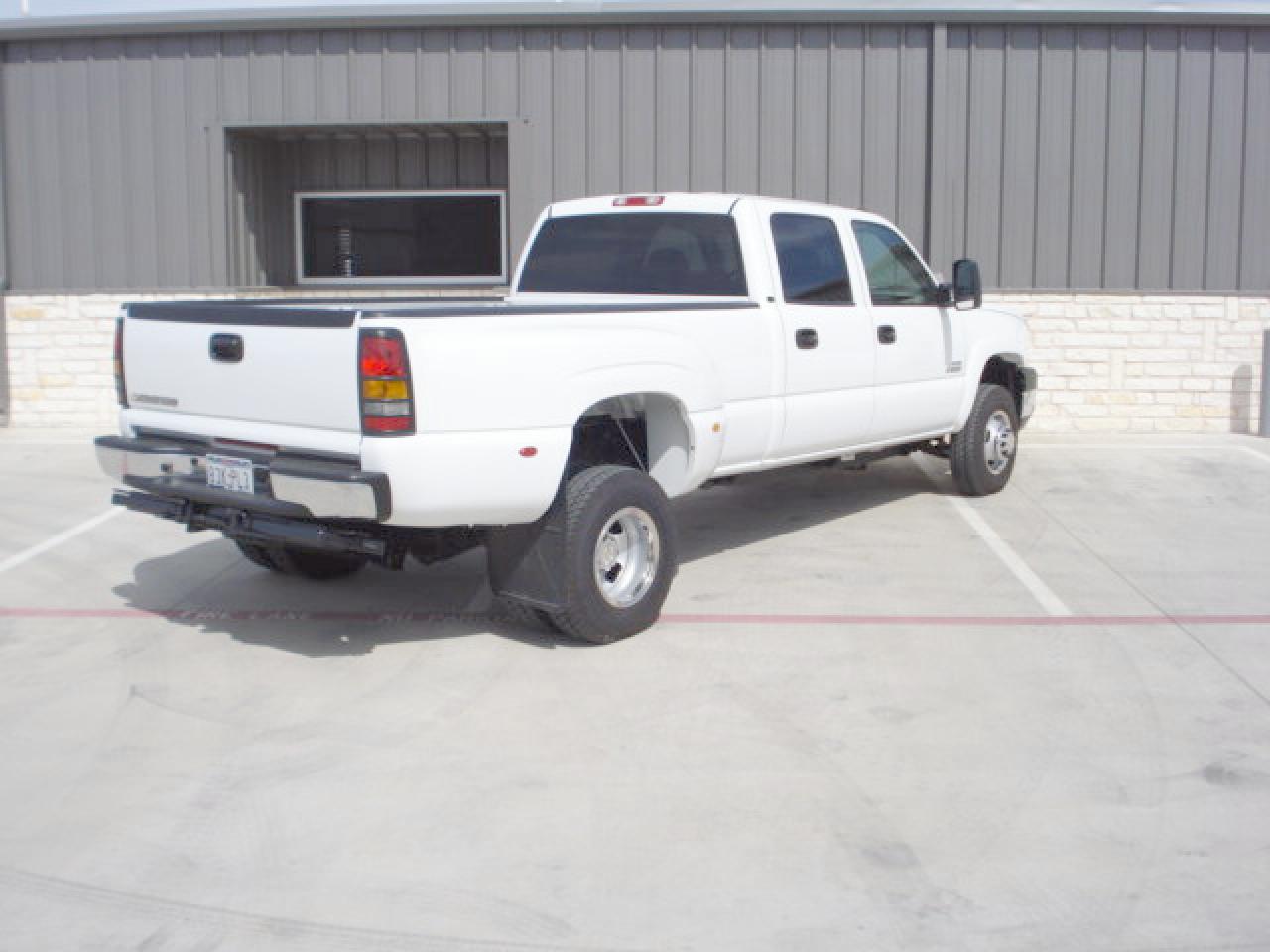 Chevy Finished Product
 Chevy 01
 Chevy 02
 Chevy Long Bed
 Chevy Short Bed
 Resevoir In Bed

 Dodge 01
 Dodge 02
 Dodge Short Bed

 Ford Finished Product
 Ford 01
 Ford 02
 Ford Long Bed